Percussion Driven Anchors
Our Falcon Anchor line provides industry-leading securing hardware for ground anchoring across civil and solar construction application (just to name a few). Falcon Anchors provide innovative, cost-effective solutions and are designed to provide immediate stabilization, requires no crimping and are have improved load-locking capabilities, for easy installation. The Falcon Anchors are pre-assembled and are available in different configurations to best meet the specified project requirements and geotechnical conditions. Installing Falcon Anchors offers the performance needed while ensuring considerable time and labor savings.

Assembly Components
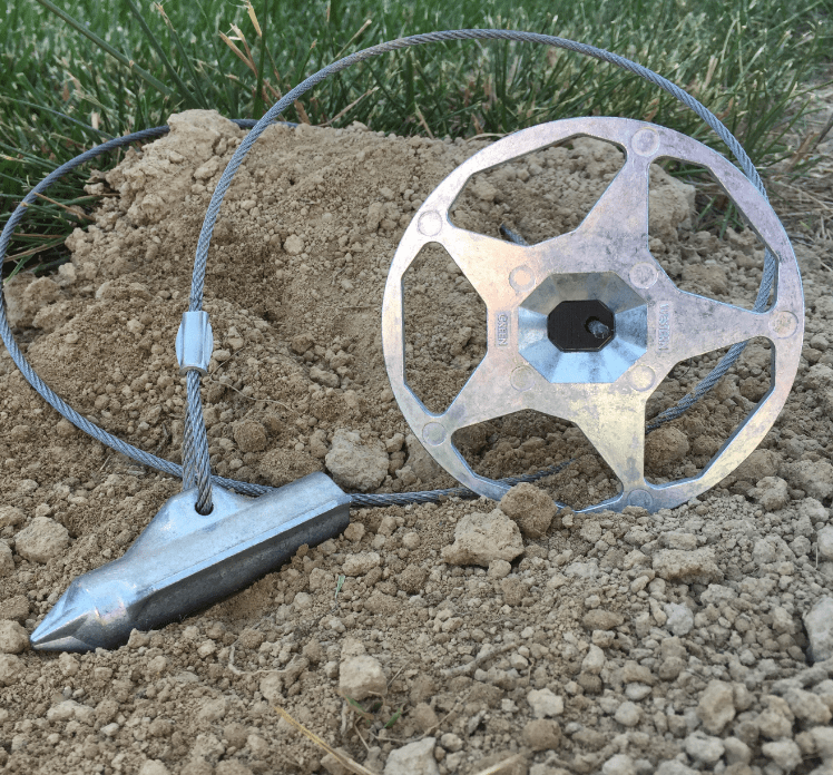
Anchor assemblies consist of four primary components:
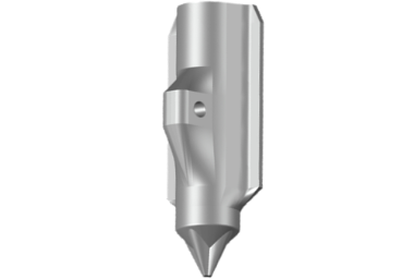
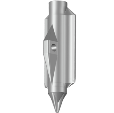
Anchor
The anchor is the component driven into the soil that develops resistance to pullout. The size, shape, soil type, soil conditions, and drive depth affect the pullout resistance of the anchor.
Top Termination
The top termination grips the ground surface and fabric to secure in place. The size of the load bearing cap effects the ability to hold the soil matrix. Openings in the termination aid in the establishment of vegetation, obscuring and protecting the hardware.
Tendon
The tendon connects the anchor and the top termination. Constructed of high-strength, corrosion resistant galvanized (zinc-aluminum coated) steel or stainless steel, the tendon is a critical piece for long-term performance. The tendon is typically fixed at the anchor side by crimping.
Grip
The grip is housed in the top termination and secures the tendon in the top termination. A release mechanism can allow for re-setting the assembly, as required.
Each of these components can be varied to provide performance and economy options.
Variants, Applications, and Performance
Anchors are available in three sizes. As the size of the anchor increases, working load and ultimate resistance increase:
F80
Zinc Die Cast
Bearing Area: 3.0 in2
F120
Zinc Die Cast
Bearing Area: 6.0 in2

F170
Zinc Die Cast
Bearing Area: 12.2 in2

For Civil construction installations with use with erosion control materials and or vegetation, the Top Terminations are available in 2 sizes. The small termination is 4” diameter (X designation), while the large termination is 6” diameter (SW designation). The top termination uses a unique design to allow for optimized working load, while still allowing vegetation establishment. Durability and working load increase with size. The termination plate is selected based on the anchor size and cabling configuration.

For ground mounting applications, such as Solar rack installation, the Top termination grip insert only (S designation) can be used. The durability and working load will be based on the anchor size and cabling configuration.
Table of Configurations
Assembly/Part | F80-X-Z Series | F120-X-Z Series | F120-SW-Z Series | F170-SW-Z Series |
|---|---|---|---|---|
Cap | 4” Dia. Zinc Alloy | 4” Dia. Zinc Alloy | 6” Dia. Zinc Alloy | 6” Dia. Zinc Alloy |
Grip | Spring-Loaded Ceramic Crush Roller | Spring-Loaded Ceramic Crush Roller | Spring-Loaded Ceramic Crush Roller | Spring-Loaded Ceramic Crush Roller |
Cable | ⅛” Dia. ZA Coated Extra Strong Steel, 3 ft Typ. | ⅛” Dia. ZA Coated Steel, 6 ft Typ. | ¼” Dia. ZA Coated Steel, 6 ft Typ. | ¼” Dia. ZA Coated Steel, 6 ft Typ. |
Anchor | 3.4” (80mm) Zinc Alloy | 4.7” (120mm) Zinc Alloy | 4.7” (120mm) Zinc Alloy | 6.7” (170 mm) Zinc Alloy |
Typ. Working Load | 750 lbs | 750 lbs | 2,500 lbs | 3,000 lbs |
Max. Working Load | 1,300 lbs | 1,300 lbs | 2,700 lbs | 3,500 lbs |
Ultimate Assembly Strength | 1,500 lbs | 1,500 lbs | 3,000 lbs | 3,800 lbs |
Ultimate Cable Strength | 2,100 lbs | 2,100 lbs | 7,000 lbs | 7,000 lbs |
Typical Use | Workhorse Light Assembly | Soft Soil Workhorse Light Assembly | Hard Soil Heavy-Duty Assembly | Heavy-Duty Assembly for Soft Soils |


Loading
PDAs are driven into the ground, typically a minimum of three feet. Once the tendon is retracted, approximately three to six inches, the anchor rotates into a load-locked position, developing the pullout resistance for the assembly. When the anchor is rotated, the geometry of the anchor creates friction in the form of a frustrum cone. The anchor can resist pullout to the limit of the friction provided by the soil mass surrounding the assembly.
Installation
The following steps illustrate the typical installation procedures for our F80-X-Z Series and F120-X-Z Series of percussion Driven anchors. Larger anchors may have additional steps for setting and securing.
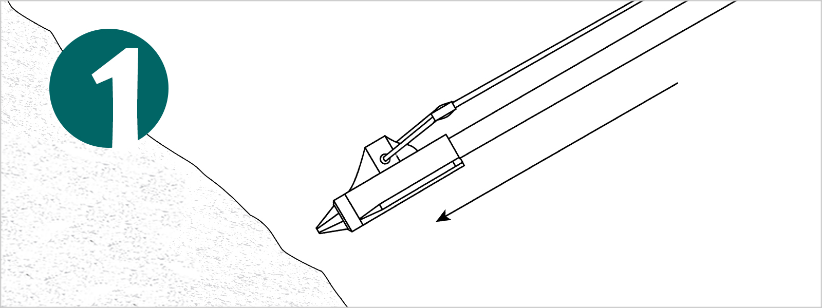
Step 1
Insert the drive rod into the Falcon anchor head and place perpendicular to the slope. Insert drive rod with anchor head swiftly through the mat in the desired location.

Step 2
Drive the Falcon Anchor to the desired depth. Anchors can be driven using sledge hammers, gas powered drivers, or hammer drills.

Step 3
Remove Drive rod. In soft soils, the drive rod can be removed hand, in tougher soils the use of a jackjaw may be required.

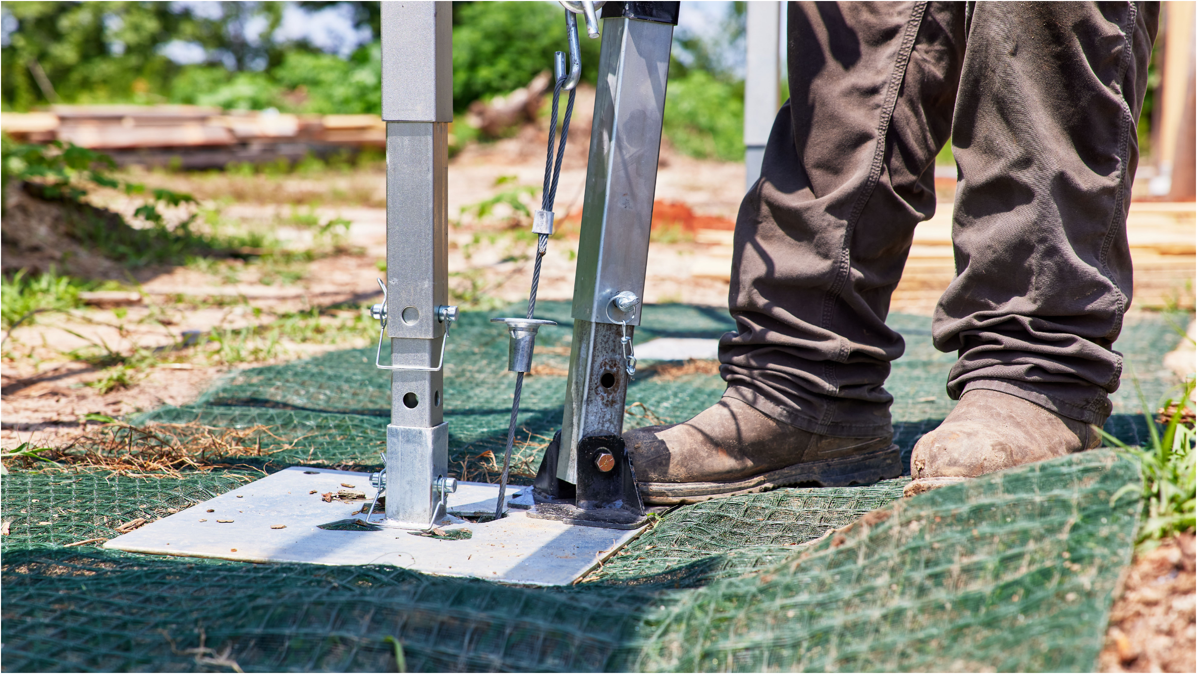
Step 4
Load lock the anchor once the rod is removed. Slide the top termination flush to the ground. Place Jackjaw baseplate directly over the top termination cap. Ensure the cable is in live with the JackJaw jaws. Handle must be in the up position to open jaws. Move the lever handle in a full down/up motion. Pump until resistance is felt. The top termination cap will appear slightly recessed in the mat once the anchor is appropriately load-locked.
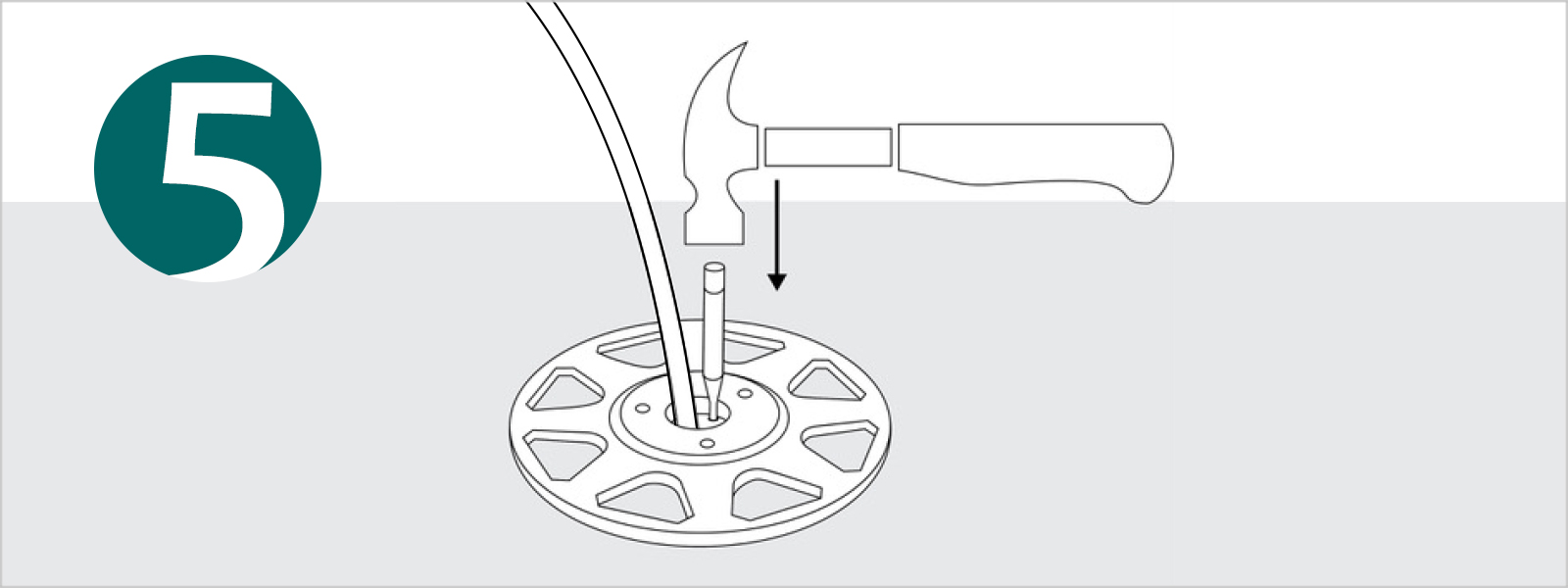
Step 5
For anchors utilizing the S or SW termination caps, manual locking of the faceplate ensures proper anchor setting even in soil conditions where fully countersinking the termination cap cannot be achieved. Using a 1/8” diameter tool with a minimum 1” depth, fully engage the locking mechanism of the top termination with a firm tap into the setting hole. Test the lock by pulling upward on the termination cap.